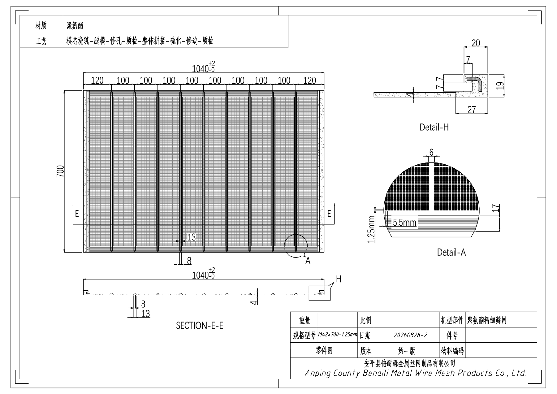
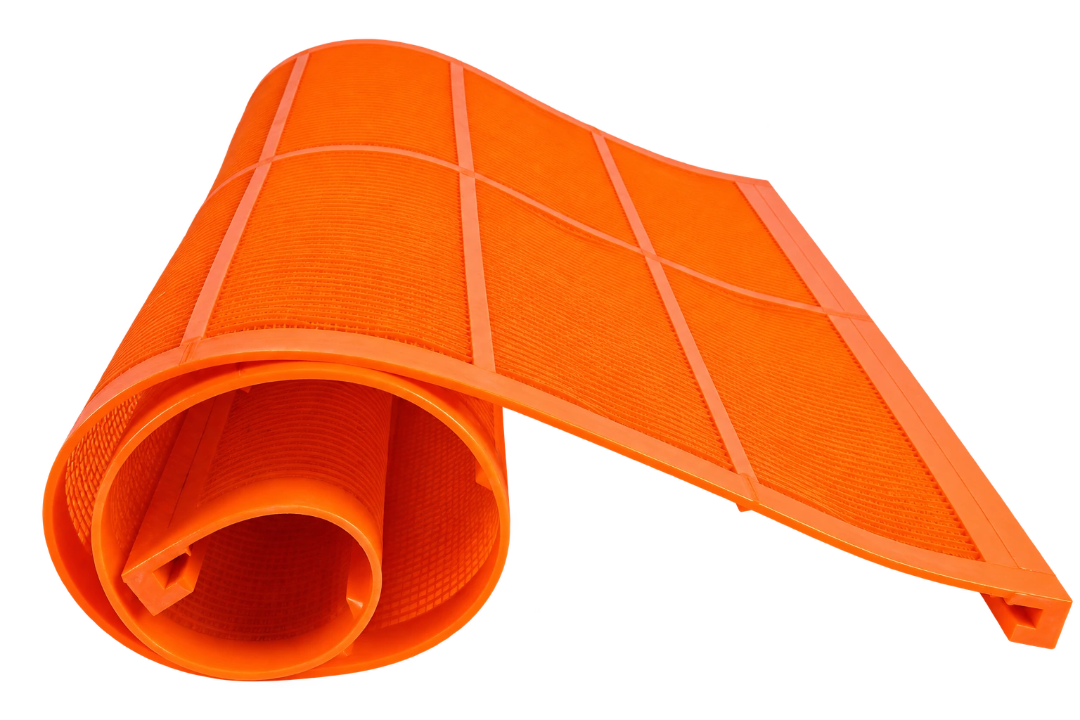
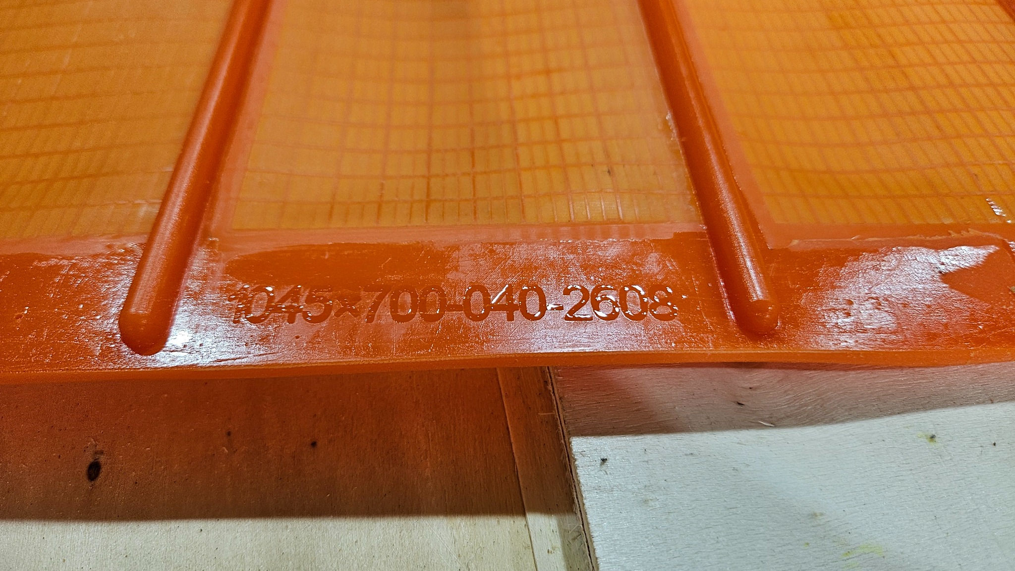
Polyurethane Fine Screen Slot Tolerance: An Inspection Checklist
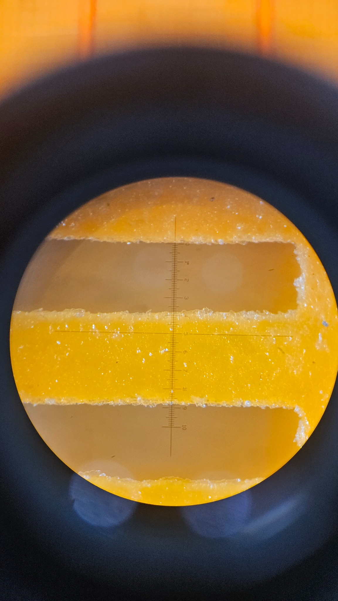
Microscope images can support an aperture inspection, but a displayed number is meaningful only when the scale, measurement location and acceptance criteria have been agreed.
Agree the acceptance specification
Write the nominal opening and permitted limits into the order or drawing. For illustration only, 0.18 ±0.02 mm means 0.16–0.20 mm, and 0.40 ±0.05 mm means 0.35–0.45 mm. These examples are not universal BENAILI tolerances or an industry standard.
Calibrate at the measurement magnification
Check the image scale with a suitable known-length reference at the magnification used for inspection. Record the calibration and units. A pixel count or a software overlay without a verified scale is insufficient evidence of the physical opening.
Define where and how to measure
Identify the working face and the intended measurement direction. Focus, viewing angle and tapered openings can affect what appears in an image. Agree measurement positions across the panel and the sampling quantity for the lot before drawing acceptance conclusions.
Keep a traceable inspection record
Record panel or lot identification, drawing revision, instrument setup, calibrated images and readings against the agreed limits. Report the sampled locations clearly: a few measurements do not prove every slot was inspected. Dimensions and material hardness are separate checks.